Instrumentationtools reversing timers modulator pulse applies oscillators diagrams Patent us8552670 3 phase motor control circuit diagram
Common Electrical Motor Controlled Circuit (2) - Power_Supply_Circuit
Motor circuit dc control circuits 12v alps diagram wiring schematic diy head idea need transistor notes Circuit motor diagram control wire phase three basics 2 wire control circuit diagram. motor control basics. controlling three
Maintenance courses
Wiring electrical contactor overload relay furnas switch 3ph starters telemecanique circuits motorer elektroteknik voltage vintagemachineryMotor control circuit software ac troubleshooting reviews circuits electrical tool machine Motor schematic diagramMotor circuit diagram control electronic pdf controller wiring installation great.
Diy students: dc motor controlMotor phase circuit control diagram wiring single works understand easily working Wiring circuitMotor control dc power diagram wiring schematic electrical circuit small component external seekic components speed ic 200v.

Motor control electrical three circuits relay diagram troubleshooting timer contactor electric starting basic circuit starter phase wiring autotransformer main hardwired
Motor circuit control diagram wiring latching simple switch contactor starter start circuits diagrams auxiliary contact instrumentation instrumentationtools tools float sponsoredControls publisher Circuit motor electrical common diagram controlled power seekic supply switch principle working icDc motor control circuit.
Forward reverse diagram wiring electrical motor control plc circuit power phase connection mitsubishi using eng elect world1 engineering ladder drawingElectrical wiring diagram forward reverse motor control and power A small motor controllerElectrical wiring motor schematic diagrams controller diagram panel electric plc example engineering circuit drawing single line symbols basic ladder transformer.

Motor circuit phase diagram control rig
How to construct wiring diagramsCircuits contactor starter allaboutcircuits solenoid pole baldor gm circuit diagrams direct bidang Motor control circuit diagram pdfMotor dc circuit control circuits 12v forum projects.
Circuit motor control electrical maintenance technician troubleshooting training software circuits program simulator plc simulation bundle cnc above screen click ebooksElectrical engineering world: wiring a motor control circuit Common electrical motor controlled circuit (2)Cnc machine tool book reviews and cnc software reviews by.

Motor circuit control diagrams wiring construct industrial
Circuit motor control reverse diagram forward electrical dol schematic star electric starter controller wiring direct delta line drawing flowchart cktWiring diagram of the electric circuit for motor control. the circuit Motor control switch logic circuits auxiliary program timer contacts ladder diagram plc forward contact open pushbutton normally programming reverse stopCommon electrical motor controlled circuit (1).
Three phase electric motor wiring diagramSmall power dc motor control component kcz1 electrical schematic Patents control circuit motorBasic electrical design of a plc panel (wiring diagrams).

How 3 phase motor control circuit works
Download electrical motor controls pdf free softwareCircuit motor diagram wiring electrical controlled common seekic deere john contactor switch km fuse principle working ac voltage A how to guide for the control circuit of a forward reverse electricMotor control circuit wiring instrumentation tools.
Circuit motors diagram two small fischertechnik controller motorMotor control circuit diagram pdf Troubleshooting three basic hardwired control circuits used in startingMotor control circuits.

DIY Students: DC Motor Control
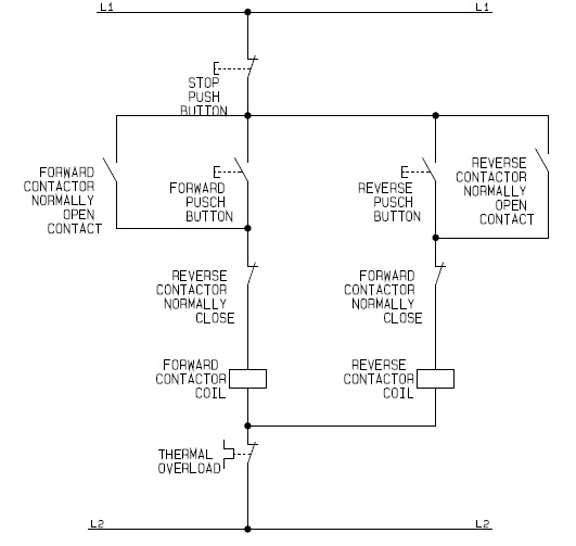
A how to guide for the Control Circuit of a Forward Reverse Electric

Wiring diagram of the electric circuit for motor control. The circuit

Motor Schematic Diagram - 1 : The circuit applies two oscillators

Troubleshooting three basic hardwired control circuits used in starting

2 Wire Control Circuit Diagram. Motor Control Basics. Controlling three

Motor Control Circuit Wiring Instrumentation Tools