Ecg amplifier noise system bandwidth low high recording frequency range ad620 simplified stability improved radio over body systems measurement electronics Ecg measurement system Circuit diagram of the pendulum driver. the op-amp (lm324) and
ECG circuit part 2A - Multisim Live
Circuit diagram consisting of 3 drl amplifiers and one complete ecg Fyp project: examples of ecg circuit Low-power wearable ecg monitoring system for multiple – patient remote
Biopotential / frequency converter composed of lm324
Circuit lm338 power circuits voltage charger battery application ic supply simple diagram regulator explained regulation current charging schematic regulated ampEcg simulator circuit using cd4521 and cd4017 Ecg circuit sikken nl schematic soundcard build below openHeart rate monitor circuit using lm358 ic.
Ecg monitor twelveEcg circuit diagram block measurement part Ecg simulator circuit cd4017 using layout figure component eleccircuitLm324 pendulum.

Ecg schematics detection signals
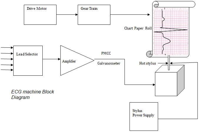
Multisim ecg circuit signal simulation software ni regarding preamp t5Ecg ad8232 circuit module Ecg diagram block machine working electronicsCircuit diagram of ecg monitor for each of the twelve leads..
Esp32 ad8232 ecg sensor iot interfacing monitoring monitoramento baseado how2electronicsSikken.nl Iot based ecg monitoring with ad8232 ecg sensor & esp32Circuit schematics for detection of each lead of the 12-lead ecg.
Ecg signal conditioning lm324 adc amplifier noise
Circuit diagram of ecg module (ad8232).Ecg machine block diagram and working ~ electronics and communication Ecg circuit part 2aCircuit ecg schematic lm741 questions begingroup.
Circuit ecg project lm324 noise cirucit fyp timeLm358 circuits explanation Regarding simulation of ecg signal in multisim softwareEcg wearable circuit low power diagram monitoring schematic analog block patient remote multiple system projectabstracts fig electronics project.

Ecg multisim
Ecg drl amplifiers consistingLm324 circuit biopotential frequency diagram composed converter amplifier seekic differential Amplifier ecgSolved simulate the following ecg amplifier circuit in.
Ic lm338 application circuitsEcg signal conditioning circuit ecg leads i, ii and iii are placed on .


ECG Measurement System

Low-Power Wearable ECG Monitoring System for Multiple – Patient Remote

Solved Simulate the following ECG amplifier circuit in | Chegg.com

ECG Signal Conditioning Circuit ECG leads I, II and III are placed on

Biopotential / frequency converter composed of LM324 - Basic_Circuit

Circuit diagram of ECG monitor for each of the twelve leads. | Download

ECG circuit part 2A - Multisim Live

Circuit diagram consisting of 3 DRL amplifiers and one complete ECG